Lumen
Lumen, a cutting-edge carrier board, specifically designed to complement and enhance the capabilities of NVIDIA Jetson modules.


General
- The Lumen introduces a powerful, yet efficient and compact edge computing solution based on NVIDIA® Jetson modules.
- Lumen introduces rich set of interfaces while maintain small footprint and minimal weight.
- The board is especially designed for unmanned systems and other space and volume constrained implementations.
Compatibility
-
The Lumen introduces a powerful, yet efficient and compact edge computing solution based on NVIDIA® Jetson modules:
- NVIDIA® Jetson Nano™
- NVIDIA® Jetson Orin™ NX
- NVIDIA® Jetson Orin™ Nano
- NVIDIA® Jetson Xavier™ NX
- NVIDIA® Jetson TX2™ NX
Resources
Mechanical
-
Weight
- Empty weight (w/o NVIDIA Jetson): 40 [g].
- NVIDIA Jetson with heatsink: ~75 [g] (estimated, heatsink dependent).
- Total Weight: ~115 [g] (estimated, heatsink dependent).
-
Dimensions
- Board dimensions are defined in millimeters.
- Mounting hole size is M2.5.

Electrical
General
- For each connector specification, the pinout orientation is determined by an arrow pointing to pin 1.
Specifications
-
Input voltage: 8-36 [V]
-
GPIO / Communication logic level: 3.3 [V]
- Warning: do not operate at any other logic voltage level.
-
Top View

-
Bottom View

Electrical pinout
- Connector orientation
-
JST-GH cables shall be oriented according to the illustration

-
Molex PicoBlade cables shall be oriented according to the illustration

-
FRC Button

- To flash,back and restore the NVIDIA Jetson module, use the FRC button according to the following steps:
- Power off the board
- hold the FRC button
- Power up the board
- release the FRC button
- The NVIDIA Jetson module is now in recovery mode
Fan

-
Connector Definition
Type Part Number Part Name Board Connector 530470410 MOLEX PicoBlade Header Cable Connector 510210400 MOLEX PicoBlade Receptacle -
Connector Pinout
Pin Name 1 GND 2 Power Output (5 V) 3 FAN_TACH 4 FAN_PWM
Power

-
Connector Definition
Type Part Number Part Name Board Connector SM06B-GHS-TBT JST-GH Cable Connector GHR-06V-S JST-GH -
Connector Pinout
Pin Name Description Voltage 1 VIN Voltage Input 8V - 36V 2 VIN Voltage Input 8V - 36V 3 VIN Voltage Input 8V - 36V 4 GND Ground GND 5 GND Ground GND 6 GND Ground GND
USB0 (OTG)

-
Connector Definition
Type Part Number Part Name Board Connector SM04B-GHS-TB JST-GH Cable Connector GHR-04V-S JST-GH -
Connector Pinout
Pin Name Description Voltage 1 VBUS OTG Power Input 5V 2 D- USB0 Data Minus 0V - 3.3V 3 D+ USB0 Data Plus 0V - 3.3V 4 GND Ground GND
UART0 / RS232
-
Connector Definition
Type Part Number Part Name Board Connector SM04B-GHS-TB JST-GH Cable Connector GHR-04V-S JST-GH -
Connector Pinout
Pin Name Description Voltage 1 VCC Power Output (5 V) 5V 2 TXD UART0 / RS232 Receive 3.3V / ±5V to ±15V 3 RXD UART0 / RS232 Transmit 3.3V / ±5V to ±15V 4 GND Ground GND -
Mode Selection
- Selecting between UART and RS232 required solder jumpers to be set.
- The diagram below shows the two possible modes:
- Green - RS232
- Purple - UART
- NOTE: when choosing UART, the RS232 Switch shall be left open.

UART1 / RS485
-
Connector Definition
Type Part Number Part Name Board Connector SM06B-GHS-TBT JST-GH Cable Connector GHR-06V-S JST-GH -
Connector Pinout
Pin Name 1 Power Output (5 V) 2 UART1_TXD (logic 3.3v) / RS485_TX_P 3 UART1_RXD (logic 3.3v) / RS485_TX_N 4 RS485_RX_P 5 RS485_RX_N 6 GND -
Mode Selection
- Selecting between UART and RS485 required solder jumpers to be set.
- The diagram below shows the two possible modes:
- Green - RS485
- Purple - UART
- NOTE: when choosing UART, the RS485 Switch shall be left open.

UART2 (Debug Port)
-
Connector Definition
Type Part Number Part Name Board Connector SM04B-GHS-TB JST-GH Cable Connector GHR-04V-S JST-GH -
Connector Pinout
Pin Name 1 Power Output (5V) 2 UART2_TXD (logic 3.3v) 3 UART2_RXD (logic 3.3v) 4 GND
I2S
-
Connector Definition
Type Part Number Part Name Board Connector SM06B-GHS-TBT JST-GH Cable Connector GHR-06V-S JST-GH -
Connector Pinout
Pin Name 1 Power Output (5 V) 2 I2S0_SCLK (logic 3.3v) 3 I2S0_FS (logic 3.3v) 4 I2S0_DIN (logic 3.3v) 5 I2S0_DOUT (logic 3.3v) 6 GND
Ethernet
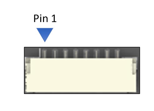
-
Connector Definition
Type Part Number Part Name Board Connector SM08B-GHS-TB JST-GH Cable Connector GHR-08V-S JST-GH -
Connector Pinout
Pin Name 1 ETH_MDI0_P 2 ETH_MDI0_N 3 ETH_MDI1_P 4 ETH_MDI1_N 5 ETH_MDI2_P 6 ETH_MDI2_N 7 ETH_MDI3_P 8 ETH_MDI3_N
CAN (not applicable when using Jetson Nano module)
-
Connector Definition
Type Part Number Part Name Board Connector SM04B-GHS-TB JST-GH Cable Connector GHR-04V-S JST-GH -
Connector Pinout
Pin Name 1 Power Output (5 V) 2 CAN_H (logic 3.3v) 3 CAN_L (logic 3.3v) 4 GND
I2C0 / I2C1
-
Connector Definition
Type Part Number Part Name Board Connector SM06B-GHS-TBT JST-GH Cable Connector GHR-06V-S JST-GH -
Connector Pinout
Pin Name 1 Power Output (5 V) 2 I2C0_SCL (logic 3.3v) 3 I2C0_SDA (logic 3.3v) 4 I2C1_SCL (logic 3.3v) 5 I2C1_SDA (logic 3.3v) 6 GND
SPI0 / SPI1
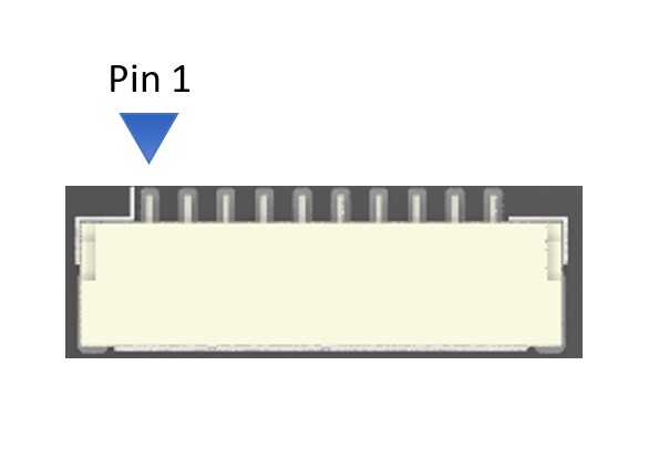
-
Connector Definition
Type Part Number Part Name Board Connector SM10B-GHS-TBT JST-GH Cable Connector GHR-10V-S JST-GH -
Connector Pinout
Pin Name 1 Power Output (5 V) 2 SPI0_SCK (logic 3.3v) 3 SPI0_MISO (logic 3.3v) 4 SPI0_MOSI (logic 3.3v) 5 SPI0_CS0 (logic 3.3v) 6 SPI1_SCK (logic 3.3v) 7 SPI1_MISO (logic 3.3v) 8 SPI1_MOSI (logic 3.3v) 9 SPI1_CS0 (logic 3.3v) 10 GND
USB1
-
Connector Definition
Type Part Number Part Name Board Connector SM08B-GHS-TB JST-GH Cable Connector GHR-08V-S JST-GH -
Connector Pinout
Pin Name 1 Power Output (5 V) 2 USB2_D_N 3 USB2_D_P 4 USBSS_TX_N 5 USBSS_TX_P 6 USBSS_RX_N 7 USBSS_RX_P 8 GND
CAM0 (MIPI-CSI)

-
Connector Definition
Type Part Number Part Name Board Connector AFA07-S15FCA-00 / 1-84952-5 - Cable Connector FFC 15 PIN 1mm pitch - -
Connector Pinout
Pin Name 1 GND 2 CSI0_D0_N 3 CSI0_D0_P 4 GND 5 CSI0_D1_N 6 CSI0_D1_P 7 GND 8 CSI0_CLK_N 9 CSI0_CLK_P 10 GND 11 CAM0_PWDN 12 CAM0_MCLK 13 CAM0_SCL 14 CAM0_SDA 15 3.3V
CAM1 (MIPI-CSI)
-
Connector Definition
Type Part Number Part Name Board Connector AFA07-S15FCA-00 / 1-84952-5 - Cable Connector FFC 15 PIN 1mm pitch - -
Connector Pinout
Pin Name 1 GND 2 CSI2_D0_N 3 CSI2_D0_P 4 GND 5 CSI2_D1_N 6 CSI2_D1_P 7 GND 8 CSI2_CLK_N 9 CSI2_CLK_P 10 GND 11 CAM1_PWDN 12 CAM1_MCLK 13 CAM1_SCL 14 CAM1_SDA 15 3.3V
SD-Card
- General
- The SD card slot is for storage only and doesn’t support flashing an operating system.
SIM-Card
- General
- The SIM card slot is intended for use with the M.2 Key B socket when connecting an LTE modem.
M.2 Key M Slot
-
General
The M.2 Key M slot is designed primarily for NVMe SSDs on NVIDIA Jetson platforms. It supports high-speed storage expansion to handle the root file systems, large datasets, AI model deployment, and fast logging, etc. This makes it particularly useful for workloads that demand fast sequential read/write speeds. -
Supported Form Factors
- 2242 Modules.
- 2230 Modules with a mechanical adapter to 2242.
-
Supported Modules
- NVMe solid-state drives (2242 form factor).
-
Implemented Interfaces (per M.2 standard)
- PCIe x4 (up to Gen 3 or Gen 4, depending on Jetson module).
M.2 Key A/E Slot
-
General
The M.2 Key A/E slot is used for wireless connectivity modules on Jetson platforms. It enables adding Wi-Fi, Bluetooth, and sometimes AI accelerator cards in compact form factors. -
Supported Form Factors
- 2242 Modules.
- 2230 Modules with a mechanical adapter to 2242.
-
Supported Modules
- Wi-Fi + Bluetooth combo cards (e.g., Intel, Qualcomm).
- AI accelerator modules.
- GNSS (GPS) modules.
-
Implemented Interfaces (per M.2 standard)
- PCIe x1 - Directly connected to the Jetson module.
- USB 2.0 - Connected over an onboard USB hub.
- I²C - Soldering the onboard jumpers routes I2C0 to this slot.
- UART - Soldering the onboard jumpers routes UART0 to this slot.
M.2 Key B Slot
-
General
The M.2 Key B slot is primarily intended for cellular modems (LTE/5G) and storage modules on Jetson platforms. When using an LTE modem, the SIM card slot on the carrier board connects to this port. It can also support certain SSDs or expansion cards depending on routing. -
Supported Form Factors
- 2242 Modules.
- 3042 Modules.
- 2230 Modules with a mechanical adapter to 2242/3042.
- 3030 Modules with a mechanical adapter to 2242/3042.
-
Supported Modules
- 4G LTE.
-
Implemented Interfaces (per M.2 standard)
- USB 2.0 - Connected over an onboard USB hub.
- SIM-CARD - Connected to the onbaord SIM-CARD slot.
Software
General
- The software installation for the Lumen board is simple and based on the same steps as the Dev Kit board.
- NOTE: The SD card slot is for storage only and doesn’t support flashing an operating system.
Environment Setup
- download and install NVIDIA SDK manager using the instructions in the following link: https://docs.nvidia.com/sdk-manager/download-run-sdkm/index.html
Flashing Jetpack OS on Jetson Nano
- Step 1: Hold the FRC button and power up the Lumen board.
- Step 2: Hold the FRC button for additional 3 seconds after power up and release.
- Step 3: Connect a USB cable to USB0 port.
- Step 4: Flash the module using the instructions in the following link: https://docs.nvidia.com/sdk-manager/install-with-sdkm-jetson/index.html
Flashing Jetpack OS on Jetson Xavier NX
- Step 1: Install SDK Manager using the instructions in the following link: https://docs.nvidia.com/sdk-manager/install-with-sdkm-jetson/index.html
- Step 2: Open the SDK Manager and select the desired Jetpack Version and target Jetson Model (the Jetson does not have to be connected)

- Step 3: Select only Jetson Linux Image and click continue, wait for the process to finish.

- Step 4: Download the Aerium Lumen BSP for Xavier NX.
- Step 5: Extract the shell script from the ZIP file and place it in the Linux_for_Tegra folder.
- Step 6: Run: sudo chmod +x Aerium-Lumen-BSP-Xavier-NX.sh
- Step 7: Run: ./Aerium-Lumen-BSP-Xavier-NX.sh
- Step 8: Hold the FRC button and power up the Lumen board.
- Step 9: Hold the FRC button for additional 3 seconds after power up and release.
- Step 10: Connect a USB cable to USB0 port.
- Step 11: Flash the module using the instructions in the following link: https://docs.nvidia.com/sdk-manager/install-with-sdkm-jetson/index.html
Flashing Jetpack OS on Jetson Orin Nano / Jetson Orin NX
- Step 1: Install SDK Manager using the instructions in the following link: https://docs.nvidia.com/sdk-manager/install-with-sdkm-jetson/index.html
- Step 2: Open the SDK Manager and select the desired Jetpack Version and target Jetson Model (the jetson doesnt have to be connected)
- Step 3: Select only Jetson Linux Image and click continue, wait for the process to finish.
- Step 4: Download the Aerium Lumen BSP for Orin Nano / Orin NX.
- Step 5: Extract the shell script from the ZIP file and place it in the Linux_for_Tegra folder.
- Step 6: Run: sudo chmod +x Aerium-Lumen-BSP-Orin-NX-Nano.sh
- Step 7: Run: ./Aerium-Lumen-BSP-Orin-NX-Nano.sh
- Step 8: Hold the FRC button and power up the Lumen board.
- Step 9: Hold the FRC button for additional 3 seconds after power up and release.
- Step 10: Connect a USB cable to USB0 port.
- Step 11: Flash the module using the instructions in the following link: https://docs.nvidia.com/sdk-manager/install-with-sdkm-jetson/index.html
First Headless Boot
- Step 1: Wait for the Jetpack to complete initial Linux configuration (up to ~10 minutes).
- Step 2: Connect a USB cable to USB0 port.
- Step 3: open Terminal and write:
- ssh nvidia@192.168.55.1
- Note: in case different username was configured during the flashing process, replace “nvidia” with the correct username.
- Step 4: When asked for password use the one configured in the flashing process.
- Step 5: You should now have terminal access to the jetson.
- Step 6 - Optional: Configure IP address and connect using ethernet cable.
- Note: In case the steps above do not work, repeat the process using debug terminal on UART2